Showing posts with label Valves. Show all posts

Tuesday, 16 September 2014

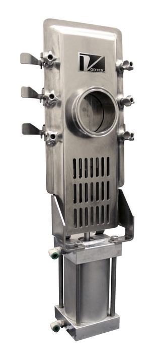
Vortex Pneumatic Diverter Valve Handling Plastic Pellets


Customer: Automotive Equipment Manufacturer

Material: Plastic Pellets

Application: Convey plastic pellets from individual storage bins to an extruder

Challenge: Replace a cumbersome hose system and automate the process of conveying multiple materials to a common destination

Valves: Vortex Quantum Wye Line Diverters | DR2.5-2AL-MG (2-way) and DR2.5-4AL-MG (4-way)

Results:

For this plastics manufacturer, the process of conveying plastic pellets was a production and safety nightmare. Flexible hoses were utilized to convey different grades and colors of pellets from storage bins to an extruder where the pellets were heated and molded into parts for the automotive industry.

The hoses took up space on the production floor. Employees moving through the facility had to be cognizant of the ever-changing location of the hoses. Production slowed down as hoses were relocated to different source bins. On occasion, hoses were connected to the wrong source material – causing the extruded parts to be rejected. It was not a pretty situation.

The company had utilized Vortex 2-way diverter valves in other parts of their facility with great success. They were pleased with the valves' performance and the exceptional life-cycle costs they provided. A decision was made to replace the hoses with Vortex multi-port diverters.

Two 4-way and two 2-way Vortex Quantum Wye Line Diverters were installed in the ceiling – routing the conveying lines off of the production floor and freeing up the floor area. Employees are now able to remotely select a source bin for the different pellets. The diverters shift into place and conveying automatically begins. All safety, production, and reject issues were solved with this new installation. The customer had the foresight to expose one of the ports of the 2-way diverters – allowing an air intake so the system can be "purged" on occasion.

"When the diverters arrived, we were surprised to see the new design of the quantum-style body. The full flange, in-line serviceability, and improved sealing features were an added bonus to a product that has always provided quality performance!" the production superintendent noted.

Contact Adroitt Flow Control, Mumbai on enquiry@adroitt.net for more information.

Tuesday, 16 July 2013

MRC Global Completes Flow Control Acquisition


MRC Global has completed the previously announced acquisition of the operating assets of Dan H. Brown, D/B/A Flow Control Products (Flow Control). Founded in Odessa, Texas in 1981, Flow Control is a leading provider of pneumatic, electric and electro-hydraulic valve automation packages and related field support, including production facilities, pipelines and plant operations, to the Permian Basin energy industry. Flow Control employs 25 people and will operate as an MRC Valve Automation Center. Flow Control reported revenues of USD 28M in 2012. "We are pleased to have completed this acquisition as part of our continued commitment to our customers in the North American Shale plays", Andrew R. Lane, MRC Chairman, President and CEO, said. "I would like to welcome Flow Control's experienced and technically knowledgeable valve professionals to our team in the Permian Basin."

METSO to launch new line of Neles Globe Control Valve in Yr 2014


Metso's new line of Neles globe control valves launched last year, which targeted the Asia Pacific, Chinese and Indian petrochemical, refining and oil & gas industries in its first phase, will be launched globally in 2014. 

The new globe control product line builds and expands on technology and service capabilities acquired when Metso purchased the South Korean company Valstone Control in 2012. 

Metso's new Neles globe valve product line is targeted at critical processes where extreme pressures and temperatures are issues. The Valstone products have been used widely in such applications in the Asia Pacific oil and gas and power industries. These customers will now have convenient access to Metso's advanced control and safety systems as well as its advanced materials and seal technologies. 

Metso's new Neles globe valve series is designed for both general and severe service applications. The top of the line severe service valves use the Omega 'Labyrinth' trim design to tackle even the toughest applications. Neles globe valves are used in various severe applications including anti-surge service. Each of the offerings is available with a variety of seat, seal, trim and actuation options to make them adaptable to a wide range of process conditions. According to See Hoe Lau, vice president of Metso Automation's Asia Pacific Sales & Services, "With the introduction of our globe valve product line to the APAC market, our customers in Asia Pacific, China and India will now be able to choose the best possible control valve solution for their applications from a broad range of products. Customers in other regions of the world will have the same opportunity when we launch the Neles globe valve line globally in 2014."


NEW ROTARY AIRLOCK VALVES FROM ACS

ACS Valves introduces a new line of cast iron rotary airlock valves designed to extend the primary process optimisation benefits typically associated with high-end, specialty-application valve designs to general industry.


This new line of ACS cast iron rotary airlock valves features the ACS RotorRail that enables tool-less access to the rotor and all internal surfaces of the housing without time-consuming disassembly of the rotor, or the removal from service of upstream or downstream equipment commonly associated with standard valve configurations.


The ACS cast iron rotary airlock valve with RotorRail has shown, when compared to bolt-together housing designs, to reduce rotor service cycle times by 78%, increasing the total process uptime by 18% during a typical 8-hour operating shift. The cast iron housings of these ACS rotary valves are cast in North America, and are CNC-machined to precise tolerances. The optimal inlet/outlet seal produced by these ACS rotary airlock valves is achieved using the standard ACS Valves' 8-vane rotor design. The ACS Valves 8-vane rotor design eliminates excess pressure loss through the system, ensures cost-efficient upstream and downstream material management, and reduces process energy consumption.


These ACS rotary airlock valves are available in sizes from 6 inches to 16 inches, with pressure differentials up to 15 PSIG, and temperature tolerance up to 500ºF. Rotor configurations include closed-end, metering, shallow-pocket, Teflon-coated and adjustable-tip. Adjustable rotor tips are available in stainless steel, hardened steel, or bronze. Interior surface coating options include hard chrome and Teflon.

Thursday, 11 July 2013

Vortex Roller Gate Valve

Vortex Roller Gate Valve - Ideal Valve

To handle powder, granules & pellets in Pneumatic & Gravity Flow Conveying

Check out this video:

http://youtu.be/ALOBI45BE7Q

The Vortex Roller Gate is the best choice for handling dry material in gravity flow or low-pressure applications. 

This gate is available in a wide variety of configurations including rectangular sizes and customer specific hole patterns. It has live-loaded seals that extend the service life by compensating for wear. These seals provide an excellent material seal across the gate and to atmosphere. They can also be replaced while the valve is in-line. Similar slide gates have seals made of soft packing, rubber or felt, which rapidly erode away allowing product leakage.


Tuesday, 2 July 2013

Vortex Orifice Slide Gate Valve - Demo


The Vortex Quantum Orifice Gate is specifically engineered to handle dry bulk solids in gravity flow, dilute phase, or vacuum conveying systems with pressures up to 15 psig (1 barg) depeding on size. Traditional slide gates and butterfly valves commonly allow packing of material, which prevents positive air and material shutoff.
Unlike common knife gates and butterfly valves, the Orifice Gate is specifically engineered to handle dry bulk powders, pellets, and granules. Knife gates rely on soft elastomeric seals which erode or tear away in service. Butterfly valves incorporate discs that cause significant flow restrictions, thus impacting system performance and throughput.  Both designs promote wedging and packing of materials, preventing positive air and material shut off. The Orifice Gate eliminates design flaws associated with knife gates and butterfly valves.

Monday, 24 June 2013

VORTEX IMPROVES SANITARY GRAVITY SLIDE GATE


VORTEX IMPROVES SANITARY GRAVITY SLIDE GATE

QuickCleanSanitaryOrificeSlideGateSALINA, KAN., USA – Vortex Valves has improved its sanitary gravity valve, the Quick Clean Orifice Gate, with improved sealing performance, higher durability, easier maintenance, and fewer replacement parts. The Vortex Quick Clean Gate is designed to handle dry bulk ingredients in the food, dairy, pharmaceutical, chemical and other industries that require frequent or daily sanitation of equipment.
 
The blade and seal design of the Quick Clean Orifice Gate allows the valve to "self-clean" on the opening stroke, even on a flowing column of material, preventing material from packing on the valve's internal seals. The gate has been redesigned to have no dead pockets or hidden areas that could lead to material spoilage or cross contamination.
 
The seals are critical to maintain cleanliness and inhibit material dust and fine powders to leak across the valve or into the atmosphere. The valve also includes hard polymer seals that compensate for wear over time. These seals also are protected from the material stream providing long service life and durability.
 
The upgraded latch assemble improves adjustability and enhances sealing. The clamp nut has been redesigned for easier and quicker rotation to loosen or clamp the nut. Its fully adjustable press lock latches allow for quick disassembly and reassembly without the use of tools.
 
The improved sanitary gate has fewer parts for easier maintenance.  The Quick Clean Slide Gate now has 13 parts compared to the original that had 24. The design improvements make the gate easier to clean and the flange-to-flange height takes up less room in a stack up within the facilities.
 
The valve, made of FDA approved materials, is USDA Dairy Standard Accepted and is also compliant with EU directives and standards.
 
Adapting the Quick Clean Orifice Gate to a system is made easy with a wide selection of actuators, flanges and tube stubs. Several intermediate position options are available allowing for precise weighing and batching. A wide variety of surface finishes are also available. Modifications can be added to accommodate a range of temperatures and corrosive, humid, or hazardous environments.

Additional Information: 
For more than 35 years, Vortex has provided quality slide gates, diverters, iris valves and loadout equipment designed specifically for handling dry bulk solids in gravity, vacuum, dilute, or dense phase applications. Vortex valves are engineered for dependability, durability, easy maintenance, and offer proven solutions to material handling and process efficiency problems. With an in-house team of engineers, Vortex products can be completely customized for individual applications or special installations.


Regards,
Anup Shah
Adroitt Flow Control Pvt Ltd
Sent from my iPhone 


MSS publishes revised and new valve standards


The Manufactures Standardization Society (MSS) has announced the following six revised standards and one new publication:

Updated/Revised Publications

  • MSS SP-42-2013, Corrosion-Resistant Gate, Globe, Angle, and Check Valves with Flanged and Butt Weld Ends (Classes 150, 300, & 600)
  • MSS SP-61-2013, Pressure Testing of Valves
  • MSS SP-81-2013, Stainless-Steel or Stainless-Steel-Lined, Bonnetless, Knife Gate Valves with Flanged Ends
  • MSS SP-123-2013, Non-Ferrous Threaded and Solder-Joint Unions for Use with Copper Water Tube
  • MSS SP-126-2013, In-Line, Spring-Assisted, Center-Guided Check Valves (Carbon, Alloy Steel, Stainless Steel, & Nickel Alloys)
  • MSS SP-130-2013, Bellows Seals for Instrument Valves

Note: SP-81-2013 and SP-126-2013 includes a revised title.

New Publication

MSS SP-145-2013, Metal Ball Valves for Low Pressure/Low Temperature Plumbing Applications

Summary: This Standard Practice establishes requirements for ball valves with CWP ratings; including pressure-temperature ratings, materials, design, dimensions, marking, and testing.


Saturday, 22 June 2013

Weir Group Acquires South Korean Valve Co HIM Tech


The Weir Group PLC has agreed to acquire a majority interest in the South Korean valves business formerly operated by HIM Tech Co Ltd ("HIM Tech").

Located in Ansan, near Seoul, the business designs and manufactures control and choke valves for severe service power generation and oil & gas applications. As well as domestic customers, its products are supplied to major South Korean engineering contractors for international projects. In the year to 31 December 2010, HIM Tech's valves business recorded sales of US$10.5m.

Weir has agreed to acquire 60% of a new Korean company, Weir International, into which the HIM Tech valves business has been transferred.

Keith Cochrane, chief executive of Weir, commented: "This acquisition in South Korea, one of the "Next 11" high growth economies, increases our global capability, allowing us to add local content in Korea and provides strong links to a number of important Korean contractors who supply both the home and international markets. The team at HIM Tech, led by Heang Hoon Cho, are already well known to us as trading partners. In recent months we have been collaborating on a number of initiatives which we expect will generate new orders for our global valves business."

Heang Hoon Cho, who will continue as president of the Ansan operation under the Weir banner, added: "I have worked with Weir for 17 years, first as agent and then licensee, and I am delighted that we are becoming an integral part of the Weir Group. The acquisition opens many new avenues to expand the business both in Korea and with Korean customers worldwide."


Tuesday, 18 June 2013

Flowserve Plug Valve Design Eliminates Maintenance

Flowserve Corporation introduces a breakthrough plug valve designed for high-pressure applications in the seawater reverse osmosis (SWRO) desalination industry. The corrosion-resistant Flowserve Durco PlugSeal allows for quick and easy repair without requiring removal of the valve from the process line, or the need for special equipment and specially trained technicians.

The unique PFA-coated plug design, an industry first, eliminates the need for a sleeve that is often difficult and expensive to remove or replace during repairs. Flowserve Durco PlugSeal can be repaired quickly — without being cut from the process line. If the valve's plug becomes worn it is easy and inexpensive to replace.

MORE INFO: www.flowserve.com


Regards,

Anup Shah

Adroitt Flow Control Pvt Ltd

Cell +91 9820501463

anup@adroitt.net

anup.adroitt@gmail.com


Sent from my iPhone

True Meaning of Double Block & Bleed Valve


It's time to do maintenance on a section of process. You don't want to shut down the entire facility, so you decide to block off and depressurize just the section you're working on. Just upstream is a double block and bleed valve—a trunnion-mounted ball valve with self-relieving seals and a bleed valve to vent the cavity. You close the ball valve and open the bleeder. Now you can de-pressurize the line downstream and open it up to work on it.

No so fast, says Rudy Garza. You may think that valve gives you double isolation, but it doesn't—and that could be dangerous.

On March 4 Garza, Mechanical Lead—Static Equipment Engineering Group at ExxonMobil Development Company, gave a presentation at the VMA Technical Seminar in San Antonio entitled "Isolation Philosophies" in which he asserted that many people take the term "Double Block & Bleed" (DBB) to mean the same thing as Double Positive Isolation" (DPI). While this may seem like a small matter, he says, it means that some users may think they've achieved positive isolation when they haven't. Part of the problem, he goes on, is that designers and users don't always understand the capabilities of the valves in question. And, he adds, the design of a particular valve can vary from one manufacturer to another.

Garza stresses that his presentation shouldn't be taken as holy writ, but as how his particular branch of ExxonMobil (i.e. Upstream) looks at the situation in its own industry and the practices it uses. Other companies (including within ExxonMobil) and industries may do things differently and it is up to the users to determine the safety and suitability of a particular practice to their application, he says.

The key message is that a user should look at the design of a particular valve, and find out exactly what the manufacturer means by the term "double positive isolation" or "double block and bleed.", to make sure it's really what's needed in a particular application.

Many users, says Garza, have taken "double block and bleed" as a generic term, and tend to use it when they really mean (and the applicable specification—API 6D, Specification for Pipeline Valves, requires) the use of double isolation and bleed. The key to understanding, Garza says, can be found in API 6D. That specification wasn't always as clear as it could have been in spelling out the difference between DBB and DPI, but the addition in 2008 of several notes has clarified it.

API 6D defines a double-block-and-bleed valve (DBB) as a "single valve with two seating surfaces that, in the closed position, provides a seal against pressure from both ends of the valve with a means of venting/bleeding the cavity between the seating surfaces." The 2008 note points out that this valve does not provide positive double isolation when only one side is under pressure.

By contrast, API 6D defines a double-isolation-and-bleed valve (DIB) as a "single valve with two seating surfaces, each of which, in the closed position, provides a seal against pressure from a single source, with a means of venting/bleeding the cavity between the seating surfaces." The note adds that this feature can be provided in one direction or in both directions.

The job of a double isolation and bleed is to stop process fluid from getting into an area where work is being done. Both in-line valves would be closed, then the bleeder would be opened. If any fluid leaked past the first valve the bleeder would drain it off before it pressurized the cavity—the space between the upstream and downstream valves, and at the same time would act as a tell-tale to indicate the leakage. If the bleeder (which is smaller than the in-line valves and may, in fact, be a needle valve) were to be plugged the downstream valve would keep process fluid from getting past it.

So why is the difference between DBB and DIB important? Let's consider a typical trunnion-mounted ball valve with self-relieving seats. API 6D defines this as a double block and bleed valve, not a double isolation and bleed valve. Under normal conditions (Figure 1) there is pressure on the upstream seal, which (along with an internal spring) keeps it energized. There's no pressure on the downstream side, so the only thing energizing the seal on that side is a spring. The bleeder valves are open, and the cavity in the ball is at atmospheric pressure.

But it's not uncommon for a valve that's been in service for a while to leak a bit. Figure 2 shows what happens then. The upstream seal is leaking a little, but this should not be a problem because the leakage will be carried away by the bleeder—except when the bleeder is not working, either because one or both of the bleeder valves is closed, or because there's a clog in the bleed line. The pressure in the valve cavity can then possibly reach as high as 200 psi, which overcomes the spring on the downstream seal and forces it off its seat, discharging fluid downstream to where people may be working. This is clearly not a double isolation and bleed valve.

So where should this type of valve be used? Figure 3 shows a situation that might occur when the valve is used in a bypass loop for proving a flowmeter, for example. The valve is closed and the bleeder is open. This time there is pressure on both the upstream and downstream seals, keeping them fully energized. This is the configuration that the API 6D definition of "double block and bleed" intended when it referred to "two sealing surfaces." But it's not true double positive isolation and bleed, as far as ExxonMobil Upstream is concerned, and in certain services, it shouldn't be used to isolate a section for maintenance.

To prevent confusion ExxonMobil Upstream sorts valves into four categories—A, B, C and D—according to the physical flow blocking capabilities of the valve and then provides guidance based on the minimum isolation requirements for a particular application, such as long vs. short term, segregation for meter proving, etc.

  • Type A is a single block valve with a single mechanically energized seal and no body bleed required.
  • Type Bis a double block and bleed (as defined in API 6D, but not always by industry). It requires pressure on upstream and downstream sides simultaneously to energize the respective seals. It's the type shown in Figures 1 through 3 (see end of article).
  • Type Cis a true double isolation and bleed (DIB) per API 6D. The valve is a single body with dual positive seals; it has a single obturator (gate, plug, etc) and dual positively energized seals (upstream and downstream) with cavity bleed port between them. It requires a cavity overpressure protection device in expansive fluid services).
  • Type D is a true double positive isolation and bleed valve arrangement, with two independent obturators (sealing members) in the same or separate bodies and two separate actuating mechanisms (i.e. independent stems). It can be made up of a pair of certain Type A, B, or C valves, either separate or built into one body. It must have a bleeder in the middle (between the two valves and between each valve's seals if Type C valves are used).

Table 1: Example valve type classifications

Type

EM Class

Ball - Floating

A

Ball - Trunnion, SRS

B*

Ball - Trunnion, DPE

B*

Ball - Rising Stem

A

Globe - (Excluding Control Valves)

A

Plug - Standard

A

Plug - Mechanically Energized Seats

C

Gate - Expanding

C

Gate - Slab

B

Gate - Sliding

A*

Gate - Solid Wedge

B*

Gate - Unported Flexible Wedge

B

Butterfly (all types)

A

* Denotes potential for exceptions based on configuration of valve and/or manufacturer

"SRS" = self relieving seats; "DPE" = double piston effect seats

Table 2 is a generic example of a filled-in requirements table. Usually there's a temperature threshold (T1, T2, etc), then a fluid characterization (flammable, non-flammable, etc.), then a pressure class (All, C1, C2, etc.), and then a size range (All, D1, D2, etc.). On the far right is the type of valve designated for that particular service (A, B, C or D). The application of the table is driven primarily by the individual facility's "isolation philosophy." The valve Type shown is risk and experience based, and it requires well documented definitions (management endorsed) for each type of valve (including variations thereof). In addition, the definition of "flammable" and "toxic" is likely to vary by company and/or location.

Table 2: Sample positive isolation format

Fluid
Design 
Temp

Fluid (examples)

Pressure or Class

Size (NPS)

Min. Valve Type (examples)

Isolation for Condition 1 (e.g. Long-Term Maintenance)

≤T1

Flammables

All

All

D

Nonflammables

>C1

All

D

≤C1

All

B

>T1

Flammables

All

All

D

Nonflammables

>C2

All

D

≤C2

All

B

Isolation for Condition 2 (e.g. Short-Term Maintenance)

>T1

All

All

All

D

≤T2

Toxic & highly 
corrosive materials

All

All

C

Flammable materials

≤C3

All

B

C4, C5 and C6

≤D1

B

Instrument connections 
with flammable 
materials

≤C7

≤D2

B

>C7

≤D2

D

Water, air and other
non-flammables

≤C8

≤D3

A

>C8 but ≤C9

All

C

All

≥C10

All

D

Isolation for Condition 3 (e.g. meter provers)

All

Specify as needed

All

All

B

Isolation for Condition 4 (etc.)

All

Specify as needed

All

All

D

Note: A "blind" can be substituted as one of the isolation points (i.e. 1 of 2 in DIB)

Remember that local regulations vary and must be kept in mind when making any valve selection.

Summary

Garza is quick to point out that the Type A, B, C and D designations are not aligned with the API 6D classifications or those of other industry standards, and are simply practices that ExxonMobil Upstream has adopted for its own use, but they bring out an important point: although block valves can stop flow, the way in which they achieve this varies and hence when specifying a valve for isolation service, don't inadvertently use a double block and bleed valve when you really need a double isolation and bleed type.

Reach Peter Cleveland at pcleaveland@earthlink.net. A longer version of this article will appear in a future issue of Valve Magazine. All images are courtesy of Rudy Garza and ExxonMobil Development Company.

Figure 1 (below). In this trunnion-mounted ball valve with self-relieving seats (which API 6D defines as a double block and bleed) there is pressure on the upstream seal, but no pressure on the downstream side, so the only thing energizing the seal on that side is a spring.

true meaning figure 1


Figure 2 (below). If the upstream seal should leak, and the bleeder is closed or clogged, the pressure in the valve cavity can overcome the spring on the downstream seal and force it off its seat, discharging fluid downstream to where personnel may have the piping opened for maintenance.

true meaning figure 2


Figure 3. This type of valve is best used where there is pressure on both the upstream and downstream seals, keeping them fully energized, as in a bypass loop for proving a flowmeter, for example. This is the configuration that the API 6D definition of "double block and bleed" intended when it referred to "two sealing surfaces," but it's not double positive isolation, as far as ExxonMobil Upstream is concerned, and it shouldn't be used to isolate a section for maintenance.

true meaning figure 3


Ready for Low - E Valve Technology


With an estimated 60% of fugitive emissions attributed to valves it is easy to see EPA's attention is on valve emissions reduction. Traditionally valve stem leakage was a visible event. Improvements in packing materials and design lead to non-visibly leaking valves.

In today's world, government regulations drive measurement of valve leakage to the molecular level in parts per million (ppm). These extremely low vaporous emissions required packing manufacturers to evaluate their product performance to the latest EPA standards for Low E Valve Packing Technology.


Definition


The terms we have become familiar with are "Certified Low-Leaking Valves" and "Certified Low-Leaking Valve Packing Technology" as defined by the EPA in consent decrees. In more current consent decrees, new valves entering will be required to be certified as "Low E Technology". A "Low-E Valve "is defined as:

"A valve (including its specific packing assembly) or valve packing for which the manufacturer has issued a written warranty that it will not emit fugitives at greater than 100 ppm, and that, if it does so emit at any time in the first five years, the manufacturer will replace the valve; provided however, that no valve shall qualify as "Low-E" by reason of written warranty unless

(i) the valve (including its specific packing assembly) either:

(a) first was tested by the manufacturer or a qualified testing firm pursuant to generally-accepted good engineering practices for testing fugitive emissions and the results of the testing reasonably support the warranty; or

(b) is as an Extension of another valve that qualified as "Low-E";

(ii) A valve (including its specific packing assembly) that:

(a) Has been tested by the manufacturer or a qualified testing firm pursuant to generally-accepted good engineering practices for testing fugitive emissions and that, during the test, at no time leaked at greater than 500 ppm, and on Average, leaked at less than 100 ppm; or

(b) Is an Extension of another valve that qualified as 'Low-E'."

This current definition of Low E Valve Technology adds test documentation to this requirement. Manufacturers have offered this warranty without supporting test data. Today there are reputable packing and valve manufacturers that can meet these low emission level requirements and documentation to assist valve manufacturers in achieving Low E requirements.


Test Protocols

Many existing test protocols are designed to measure the performance of valves and packing products. The two most commonly used protocols are API standards and ISO 15848-1. The API standards utilize methane as the media and Method 21 to measure emissions while the ISO test typically uses helium as the media with vacuum as the leak detection method. It is important to note the EPA only recognizes emission testing conducted utilizing Method 21.

API 622 fugitive emissions test protocol evaluates the performance of a valve packing in a specified test fixture, number of strokes and temperature cycles while monitoring emissions in ppm. This protocol allows for average leakage measurements up to 500 ppm and one retorque throughout the test. The test is not a pass or fail, but determines if a packing completed the test without exceeding these limits.

The API 624 valve fugitive emissions test protocol is soon to be published. This standard sets the limit of 100 ppm emissions from the valve and no retorques are allowed. The standard also requires valve manufacturers to use an API 622 tested and qualified packing in this test. Not all API 622 qualified packings will be able to meet the API 624 requirements.

Starting with a valve packing qualified to API 622 with a maximum leakage of below 50 ppm and no retorques is important. Factors such as surface finish, tolerances and valve design will affect packing performance. When selecting a packing that has a maximum leakage of below 50 ppm allows for these factors and gives the valve manufacturer a better chance of meeting the API 624 requirements.


Converting to Low E Technology

As a valve manufacturer, adapting the Low E Technology as a standard for your equipment puts you in the position to provide the latest in valve packing sealing. Since Low E packings seal to such a tight standard, using them for all services allows you to offer the latest in sealing technology to all your users. A few forward thinking valve manufacturers have taken the lead to convert all their valves to Low E Technology. This is a benefit to their customers with a variety of valves ( some requiring Low E technology, while others are exempt as they are not in VOC and VHAP services). This standardization minimizes confusion and the need for the customer to keep two sets of valves (one for Low E services and one for all others). It also prevents installing the wrong valve in a Low E Technology required process.

Valve and packing manufacturers have the opportunity to be proactive in supplying Low E Technology to their customers. The EPA is knowledgeable of the current state of Low E technology and will no longer accept the argument that low emission valve technology is unavailable. Incorporating Low E Packing in your valves addresses the growing need in the emissions valve market as more consent decrees are issued and EPA enforcement is stepped up.


Walter S. Moquin is currently Manager of Business Development for Mechanical Packings and Gaskets with the A. W. Chesterton Company where he oversees the business for pump and valve packings. Moquin has conducted technical equipment reliability seminars and training regarding process systems and components. He was also responsible for field testing of new products, failure analysis, and application engineering. He currently is involved with Chesterton's Valve Emissions Program and working with the EPA, end users and valve OEMs to better understand Low E packing technology. He can be contacted at moquinws@chesterton.com


DeZURIK announces new President & COO

DeZURIK, Inc. has announced the appointment of Bryan Burns as its new President and Chief Operating Officer. Theannouncement was made today by Larry Korf, Chief Executive Officer of DeZURIK, Inc. and will take effect immediately. As part of this planned DeZURIK leadership transition, Korf will retain his position as CEO and has accepted a position on the DeZURIK Board of Directors.

Burns joined DeZURIK in 2010 as VP of Operations and was promoted to Chief Operating Officer in January 2012. Previously, Burns was employed by the Brunswick Corporation, where he was President of the Crestliner Division. He is a graduate of Pennsylvania State University and earned his MBA from Duke University.  


ValvTechnologies opens new facility in India

ValvTechnologies has opened a new assembly and global sourcing facility in South Indian Metro City, India, to meet growing demand for its valves and to help reduce logistics costs for customers in the Middle East, Asia and Australia.

According to Prabhakar Seetharaman, Managing Director, ValvTechnologies Private Limited, the new plant will produce 100 to 120 valves per month with initial focus on the company's V1 Series valves.

"Our new India operation will serve as the hub for ValvTechnologies sourcing in this part of the world," explained Seetharaman. "With onsite vendor selection, project monitoring and product inspection, our customers will see reduced costs and faster delivery. This is key to growing our sales in Australasia."  


Regards,

Anup Shah

Adroitt Flow Control Pvt Ltd

Cell +91 9820501463

anup@adroitt.net

anup.adroitt@gmail.com


Sent from my iPhone

Noise from Cavitation - Bad for Valves & Equipments

noise from cavitation 1Just as sound can have negative effects on the human body, certain frequencies can play havoc on industrial equipment. When control valves are not selected appropriately, there is an increased risk for cavitation, which causes high noise and vibration levels, resulting in very rapid damage to the valve's internals and/or the downstream piping. In addition, high noise levels usually cause vibration that can damage piping, instruments and other equipment.


Negative Effects on Control Valves & Equipment

Along with degraded control capability and rapid deteriation of the control valve itself, valve generated cavitation can cause serious damage to the piping system in which it occurs. Most of this damage is caused by vibrational noise energy, accelerated corrosion, and process contamination.

The high noise levels associated with cavitation reflect the large-amplitude vibrations generated by the formation and collapse of vapor bubbles near and downstream of the vena contracta.

noise from cavitation 2While this normally occurs within the valve body in globe and rotary plug valves, it can actually occur in the piping downstream of a short, high-recovery valve like wafer-body segment (V) ball valves, large ball valves and especially butterfly valves. When these valves are miss-applied in a location prone to cavitation, it is not uncommon for the piping downstream of the valve to be covered with weld-repaired leaks, or for this section of pipe to be frequently replaced as it fails.

Regardless of whether the cavitation occurs inside or downstream of the valve, equipment downstream of the cavitation zone can see extensive damage. The large-amplitude vibrations can excite oscillatory failure in thin diaphragms, springs, and small cross-section or cantilevered structures. Frequent points of failure are found in instrumentation such as pressure gauges and transmitters, thermowells, flow meters, and sampling systems. Heat exchangers can fail prematurely from fatigue as the heat transfer fins oscillate due to vibration. Check valves, actuators, positioners and switches that contain springs will suffer accelerated wear, and mounting brackets, fasteners and couplings will loosen and fail because of the vibration. Unfortunately, hydrodynamic noise propagates extremely well in liquids and metal pipe walls, so it can take hundreds of pipe diameters for the noise to dampen to non-dangerous levels once it occurs.

noise from cavitation 3A globe control valve plug that has been damaged by cavitationFretting corrosion, which occurs between wearing surfaces exposed to vibration, is common near cavitating valves. This generates hard oxides which act as abrasives to accelerate wear between the wearing surfaces. Equipment affected includes isolation and check valves in addition to the control valve, pumps, rotating screens, samplers and any other rotating or sliding mechanism.

The high-amplitude vibrations also microscopically flex the metal valve parts and pipe walls, encouraging grain-boundary cracking and corrosion. The solid particles and corrosion chemical by-products released represent potential contaminants to the process. For instance, if the process is a RODI water treatment loop, a food or pharmaceutical process, a paper pulp bleaching line, or any number of high-purity processes, these contaminants degrade the quality of the product.


Predicting & Eliminating Cavitation Damage

Especially with rotary valves, the prediction of damaging levels of cavitation is more complex than simply calculating the choked flow pressure drop. Experience has shown that there are likely to be areas of localized vaporization and vapor bubble collapse before the pressure in the main flow stream drops to the vapor pressure of the liquid. Some valve manufacturers predict the beginning of cavitation damage by defining an incipient damage pressure drop. One valve manufacturer's method of predicting the beginning of cavitation damage is based on the fact that it is vapor bubble collapse that causes both cavitation damage and noise. This manufacturer has determined that if calculated noise levels are below the following limits, significant cavitation damage will be avoided.


  • Up to 3 inch valve size – 80 decibels (dBA)
  • 4-6 inch valve size – 85 dBA
  • 8-14 inch valve size – 90 dBA
  • 16 inch and larger valve size – 95 dBA

Methods of eliminating cavitation damage include both valve style selection and process modifications. Special valve designs for eliminating cavitation employ flow division and pressure drop staging, sometimes individually and sometimes together. 'Flow division' divides one large flow into a number of smaller flows by designing the flow path in the valve so that the flow passes through a number of small parallel openings. This is effective because the size of the cavitation bubbles is partly a function of the size of the opening the flow is traveling through. Smaller openings make smaller bubbles, which results in less noise and less damage when they collapse.


Pressure drop staging means that the valve is designed to have two or more throttling points in series, so that instead of taking the entire pressure drop in a single step, it is taken in several smaller steps. Smaller individual pressure drops can prevent the pressure at the vena contracta (the point where the velocity is the highest and the local pressure is the lowest) from dropping to the liquid's vapor pressure, thus eliminating cavitation. Improved cavitation resistance can be obtained by combining flow division and pressure drop staging in the same valve.


Modifying the process to locate the control valve where the pressure at the valve inlet is higher (such as farther upstream or at a lower elevation) can sometimes eliminate a cavitation problem. Also, locating the control valve at a location where the liquid temperature, and thus the vapor pressure, is lower (such as the low temperature side of a heat exchanger) can help eliminate a cavitation problem.


Summary

As has been shown, cavitation in control valves does more than just degrade valve performance and damage the valve. Downstream piping and equipment is also at risk, and process contamination can ruin the product that the process is intended to make. Predicting cavitation and taking steps to eliminate it is the only way to avoid a costly and ongoing problem.


Jon Monsen, Ph.D., P.E., is a Control Valve Technology Specialist at Valin Corporation, specializing in technical training and assisting Valin's customers in the proper application of control valves.


Peter Jessee, P.E., is an Application Engineer at Valin Corporation providing sizing, selection and recommendations of process valves and instrumentation to Valin's customers and personnel.  


Regards,

Anup Shah

Adroitt Flow Control Pvt Ltd

Cell +91 9820501463

anup@adroitt.net

anup.adroitt@gmail.com


Sent from my iPhone